Radii of curvature are a critical aspect of horizontal directional drilling from several perspectives. Whether in relation to product pipe radii, design radii, or as-built radii, understanding this aspect of the HDD method is vital – as it’s critical to good design, practical and feasible application of the HDD method, and, ultimately, the overall success of the HDD.
What are radii?
To understand radius of curvature, take a circle:
- The centre of that circle is the “centre of curvature”.
- The circumference of the circle, or any arc which makes up part of it, is its “curvature”.
- The radius of that circle – ie, from the centre to the circumference edge – is the “radius of curvature”.
A direct relationship exists between the length of the radius and the degree of curvature of its associated circle/arc. Shorter radii result in smaller arcs and a higher degree of curvature – ie, tighter curves – and longer radii result larger arcs with lower curvature.
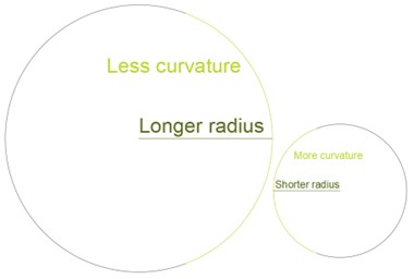
Figure 1: Relation between length of radius and degree of curvature.
Why is radius of curvature important in HDD?
In relation to HDD, radius of curvature of three specific aspects are relevant:
- Minimum product pipe bend radius (or “product pipe radius”).
This is the shortest radius of curvature – ie, the tightest bend – that the product pipe may be subjected to while still retaining its suitability for use.
- Design minimum radius of curvature (or “design radius”).
This is the shortest radius of curvature that can be incorporated into the HDD design whilst staying within the constraints of the crossing and retaining acceptable constructability.
- Minimum acceptable as-built radius (or “as-built radius”).
This is the shortest radius of curvature that is allowable over a length of any three drill pipes drilled in the pilot bore (as measurements from the pilot are used to prepare the as-built in the vast majority of HDDs). Usually defined in the project HDD specification, this is also known as a “3-joint radius”. It sets a limit for allowable deviation from the design radius in the actual-as built radii.
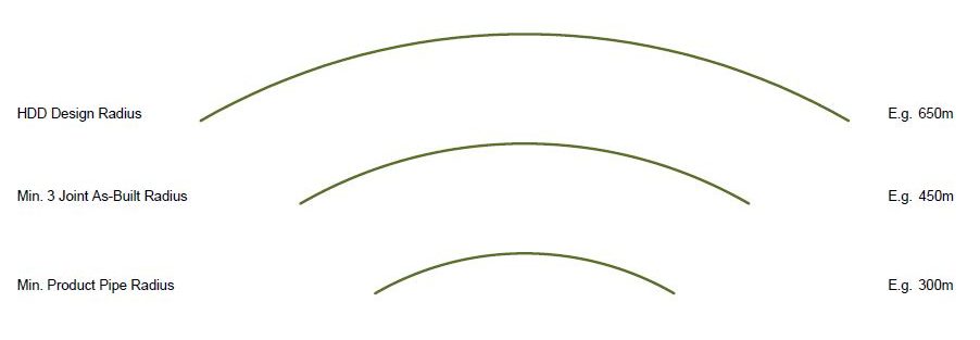
Figure 2: Comparison of typical HDD radii, with product pipe radius the smallest, design radius the largest, and as-built radius in between.
What needs to be considered when determining suitable radii?
A wide range of factors must be taken into account when determining suitable radii for an HDD project, such as the following:
- Determination of the product pipe radius is recommended as a first step, as maintaining compliance with the product pipe’s minimum allowable radius is critical to its operational suitability.
- Determining product pipe radius requires assessment of several factors, such as its specifications (material, wall thickness, diameter, etcetera), minimum/maximum operating temperature, operating pressure, and so on.
- This minimum radius cannot be surpassed – ie, a shorter radius delivered – without serious repercussions for project outputs and outcomes, such as irreparable damage to the product pipe. As such, this radius then provides a strict baseline for determining the other radii.
- Design radius can then be assessed.
- Again, several crossing-specific factors must be considered, such as drill pipe bending capacity, ground conditions, topography, capacity of the opted downhole tooling to navigate the ground conditions and HDD geometry (ie, a long BHA including a mud motor will be less manoeuvrable around tighter radii than a shorter jetting assembly), and of course the product pipe radius, which should already be known. Maximum depths for product pipe installation, available easements, and many other factors may also constrain the design radii.
- Product pipe minimum bend radius may be less than drill pipe bending capacity in some instances, and more in others, depending on individual project factors. For example, HDPE product pipe can generally bend to smaller radii than drill pipe, but large-diameter steel product pipe may have less bending capacity than drill pipe. Different drill pipe also has different bending capacity, so it must be considered for each crossing.
- Again, design radii must always be larger than product pipe radii, to ensure the product pipe’s operational suitability is not put at risk. To ensure that the product pipe minimum radius is not approached during delivery, a suitable safety factor must be applied when defining the design radii. More on that later.
The factors which are relevant to determining suitable design radii differ widely from HDD crossing to crossing. A single factor may affect design radii significantly – meaning that a radius that worked in one crossing may be too small in another one, even if both crossings are very similar. Conversely, smaller design radii may be completely fine in another similar crossing, due to differing factors. And it’s important to remember that in highly constrained HDDs, compromises may need to be made to ensure that constructability is prioritised.
Where does as-built radius come in?
We are often asked to determine a suitable as-built radius for particular HDDs, or to assess the suitability of one which has already been determined. We’re sometimes asked, “Shouldn’t the as-built radius just be the same as the design radius?”
The answer to this is no. When it comes to radii, there will always be variation between what is defined in a design versus what is completed on site, as what is defined on paper simply cannot be delivered as precisely in practice. This is because it’s real life: actual drilling radii are routinely affected by a variety of factors on site and the limits of the HDD method, which can cause deviation from the design radius. The as-built radius simply adds an allowance for “real-life factors”, clearly establishing the permissible amount of reduction from the design radius in any 3-joint length. This communicates clear thresholds for the contractor, providing suitable leeway for them to deliver a compliant pipeline – ie, how much smaller a radius can be while still remaining “compliant”. As such, the minimum acceptable as-built radius is less than the design radius.
What are these “real-life factors” which can cause variation from the design? As-built radii can be affected by many factors, including:
- Ground conditions. Ground conditions are generally the single most significant factor resulting in deviation from design. For example:
- Harder than expected ground conditions can result in difficulty with the BHA navigating curves, and thus larger than expected radii.
- Transitioning from soft conditions to hard conditions can result in a smaller radius due to abrupt deflection of the drill bit when hitting the harder layer.
- Soft conditions can cause difficulty in achieving sufficient weight on bit to enable steering, resulting in larger radii.
While larger than expected radii are generally not an issue (as long as the trajectory is corrected to “average out” and remain consistent with the design profile and alignment), smaller than expected radii can be.
- Equipment capability and condition. Although a specification sheet may state that a particular piece of equipment can achieve a particular radius, this is generally best-case scenario. If not brand new and under optimal conditions, performance may be affected.
- Steering latency. Steering latency – ie, the distance of the steering probe behind the bit – necessitates the steerer to make reasonable estimations as per expected conditions to maximise consistency with the design profile and alignment, and increases complexity in establishing a steering pattern. In particular:
- Steering latency is more pronounced in some HDDs than others. In particular, latency is most significant when using magnetic steering and a mud motor, due to the probe needing to be housed behind the mud motor, 10+ metres behind the bit. When the steerer takes a survey shot, that tells them where the probe is, not the bit. They will need to drill another 10+m and take another survey shot to know where the bit was at the original survey point. And if at that point it becomes apparent that deviation from the intended design is occurring, adjustments can only be made from that point onwards – thus the steering “lag” or latency (unless the steerer wishes to retract the steering assembly, side track, and re-steer). Long story short: the precise location of the bit isn’t known – we are only able to know where it was, and make educated estimations of where it is. This is another reason that HDD steering is known as “tracking” – as the probe “tracks” where the bit has been, not where it is now. As such, the steerer must study the ground conditions, establish a steering pattern, and make reasonable assumptions and adjustments in order to pre-empt issues that may affect the steering and maximise compliance with the design.
- Part of minimising steering latency, as mentioned above, involves establishing a steering pattern, usually initially in the first few joints of the HDD. As all ground conditions are different, in all HDDs, the steerer must determine how much, and how, the ground and other conditions are affecting the steering, and thus how much, and how, the steerer must adjust their steering directions to account/correct for the conditions and maintain consistency with the design – and this should be achieved as soon as possible. For example, if a 10° entry angle section is required, a 10° angle might be programmed to be drilled by the steerer. However, after drilling one joint and taking a survey shot, the steerer may find that the actual angle being achieved is only 9° – which routinely happens for many reasons, particularly ground conditions. As such, they will adjust their steering to account for the onsite factors that may be affecting the steering – programming 11° (accounting for the extra degree of deflection, for example) in order to hopefully achieve the desired 10°. These adjustments are made until a consistent pattern is achieved and steering becomes more predictable. It’s important to note, however, that this is a very simple example: many, many adjustments by the steerer may be needed to establish a consistent pattern, and if the probe is a long distance behind the bit, the “lag” means that significant distance may need to be traversed, and many adjustments made, before a reliable pattern can be established. And of course, as ground conditions change – such as when the pilot hole reaches deeper, harder layers – the steering pattern may need to be readjusted. Incidentally, establishing a steering pattern is made more simple if an initial straight section is included in the HDD, providing the steerer with a consistent baseline in which to establish their steer pattern.
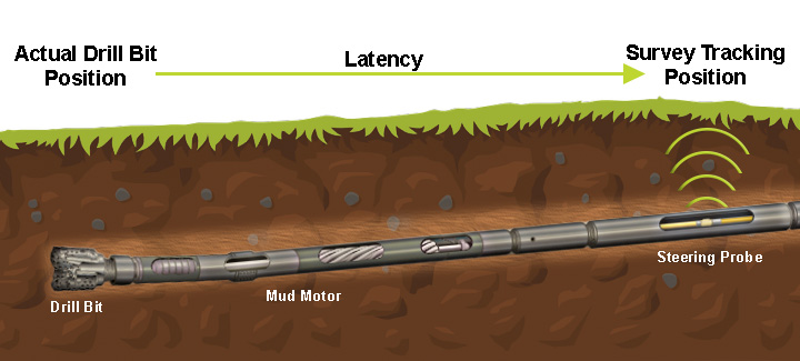
Figure 3: Steering latency explained. The steering probe may be several metres behind the drill bit and is thus “tracking” where the drill bit has been, not indicating where it is currently.
It’s important to remember that on-site factors may result in deviation from design radius in either direction – ie, smaller or larger radii than intended may be incurred for a variety of reasons – and that this can be significant. In fact, ASCE Pipeline Design for Installation by Horizontal Directional Drilling states that “it would not be unusual to find deflections in a pilot hole that produced a bending radius approaching 50% of the design radius”. And of course, it’s not as simple as just applying blanket conservatism in steering in order to not go less than the allowable design radius – ie, for a design radius of 500m, instead steering to 550m. This is because steering is generally also subject to an allowable design tolerance – for example, steering must not deviate from the design profile/alignment by more than “X” millimetres in any direction. So any deviation as a result of being conservative in order to avoid as-built radius nonconformity would likely result in deviation from allowable steering tolerance – not to mention an HDD which could be significantly different from that which has been designed.
So, how do we ensure appropriate radii for an HDD?
To ensure radii for an HDD crossing are appropriate is simply a matter of prioritising the product pipe radius, understanding the HDD method and how it can be affected on site, and applying suitable safety factors for design and delivery. The following steps are critical in doing so:
- Effective determination of product pipe radius – the “do or die” radius which sets an absolute minimum size radius that cannot be surpassed (ie, a smaller radius delivered). This must be known to ensure a suitable safety factor can be applied in design and the product pipe radius is not approached.
- Effective determination of known factors that constrain the HDD, and thus setting design radii which should realistically be achievable on site, including a suitable safety factor. As a rule, if a suitable safety factor has been applied, design radius should be significantly larger than product pipe radius.
- Establishment of a suitable as-built radius which sets the limits for the contractor to deliver a compliant HDD – basically, defining a reasonable amount of deviation from the design radii when allowing for onsite factors and the realities and limits of the method.
What happens when radii are not complied with?
Consequences of radii being surpassed in practice – ie, radii delivered which are smaller than the limit allows – depends on which radius we’re talking about, and by how much. Each project differs, and all radius nonconformity must be judged on an individual basis, but generally, the following generalisations can be made:
- Actual as-built radius less than minimum allowable as-built radius.
An instance of this may or may not have practical implications. While officially nonconforming, the practical consequences of the nonconformity depend on the degree of deviation.
- Generally, if the actual as-built radius is smaller than the allowable as-built radius but still significantly larger than the product pipe radius, practical effects on the pipe may be assumed to be nil.
- If the actual as-built radius is smaller than the allowable as-built radius and approaching the product pipe radius, there may be practical effects on the pipe. These effects become more likely the closer the product pipe radius is approached. If the product pipe radius is exceeded, consequences are more serious – details of that below.
- Actual as-built radius less than product pipe radius.
An actual as-built radius which is smaller than the product pipe radius may have severe consequences. The major issue is that by subjecting the pipe to a bend which is more than recommended, its operational effectiveness may be jeopardised, and it may be damaged and no longer be fit for purpose. That said, a few caveats exist:
- As-built radius is generally measured from pilot hole, not final pipe position. Because an HDD borehole is reamed to a larger diameter (commonly 1.5 x the product pipe size), this process “smooths” the borehole geometry to a degree, as well as creating more space in the borehole than the product pipe needs. Thus, when the product pipe is installed, it settles in this larger annular space in a more “relaxed” position than it appears on the as-built. This can mean that a tight radius on an as-built drawing may not result in the pipe being as tightly curved as indicated.
- To determine the final position of the product pipe, and whether the noncompliant as-built radius is also applying to the pipe, survey of the installed pipe using a survey pig can be conducted. Gauging of the pipe with a gauging pig can also be conducted to determine if internal damage to the pipe has occurred. However, each of these options would be last-case scenario, generally only at the project client’s discretion, and not conclusive. Otherwise, the pipe would be deemed unsuitable for use, and a re-drill and replacement product pipe could be required.
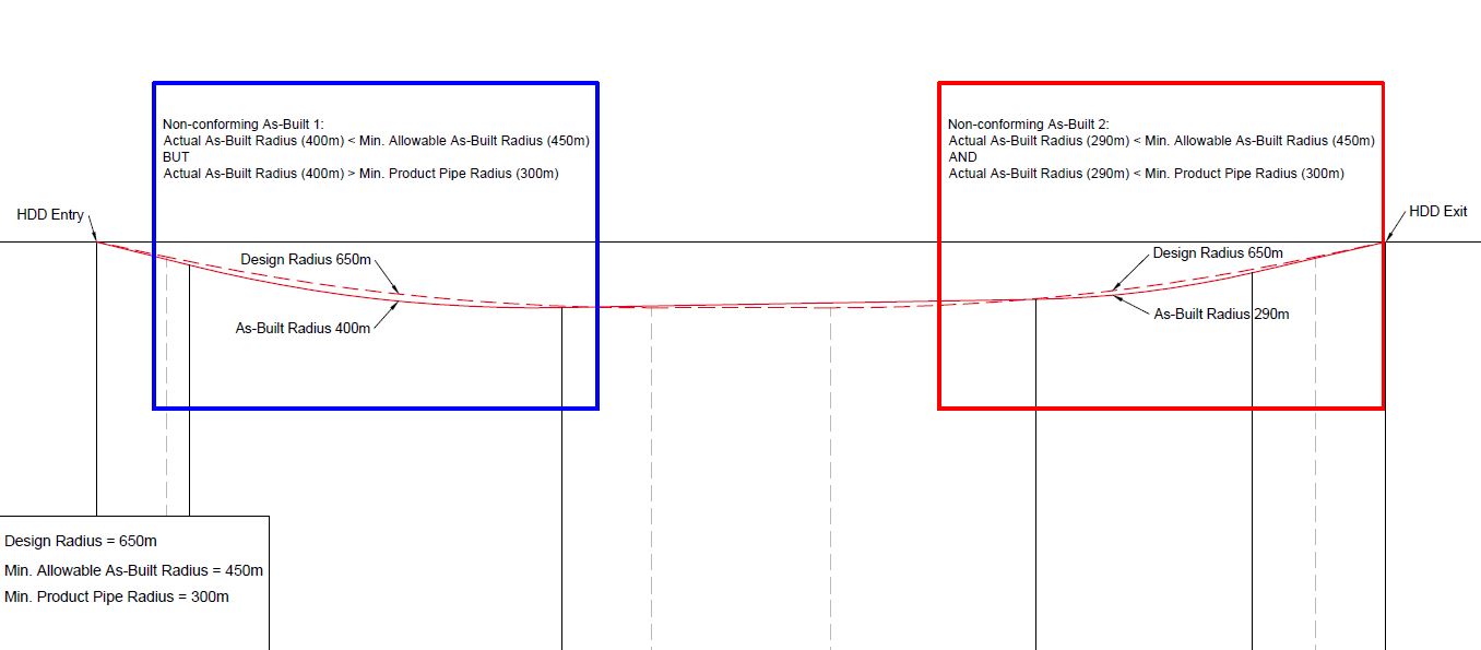
Figure 4: Two nonconforming as-builts with two very different outcomes. With Nonconforming As-Built 1, allowable as-built radius has been exceeded, but product pipe radius has not, thus damage to the product pipe is improbable, and nonconformity is likely of little consequence. However, with Nonconforming As-Built 2, product pipe radius has also been exceeded, and thus the product pipe may be irreparably damaged.
Conclusions
Radii of curvature are critical to HDD projects, and the different radii of curvature fulfil different roles. Knowing the functions of these radii, how they are determined and affected, how they relate to each other, and the consequences if they are exceeded, is vital to decision-making and HDD crossing success.
- The most important aspect in relation to radii is to ensure that minimum allowable product pipe radii are not exceeded – ie, a smaller radius delivered – as doing so can cause irreversible damage to the pipe and affect its operational suitability.
- Design radii must include a suitable factor of safety which allows for on-site factors and the limits of the HDD method, to outline a design which is constructable in practice and prevents the minimum product pipe radius being approached or exceeded (assuming that good drilling practice is followed). Design radii must also take into account on-site factors such as ground conditions, equipment limitations, and so on, and they may be constrained by several factors, such as topography, available easements, and depth limitations. Basically, determining suitable design radii must weigh up all the constraints and factors which limit and may affect practical delivery of the crossing, and arrive at the best-case scenario for delivery of the crossing. It’s important to remember that for highly constrained HDDs, compromises may need to be made to prioritise constructability.
- Allowable as-built radii set a limitation by which the minimum design radii may be exceeded – ie, a radius smaller than the design radius delivered – over any 3-joint length of the HDD. As construction of an HDD is a real-life operation that is subject to many factors on site, it can never be delivered as precisely as the design, and leeway is necessary. The as-built radius simply defines how much deviation is acceptable – ie, how much smaller the as-built radius is permitted to be than the design radius.
- If radii are exceeded – again, a smaller radius delivered – practical implications differ depending on which radius has been exceeded, and by how much. Exceeding an allowable as-built radius, while still technically noncompliant, may have zero practical consequences if the product pipe radius has not been approached and/or also exceeded. However, if the product pipe radius has been approached or exceeded, practical consequences may be very serious.
- Applying adequate safety factors in design radii and as-built radii can assist with preventing product pipe radii being approached or exceeded, but this is always a balance with many competing factors.